An affordable do it yourself active loop antenna that covers 15KHz to 32MHz and probably more, is roughly represented by the following sketch.

To further describe this antenna shown in the sketch, it is 1 meter in diameter more or less, and the coax could be any coax that is available. I used a foam filled RG8 which is very flexible and doesn’t hold a shape. LM400 or other solid dielectric coax should be a better choice. I was experimenting on this build and I’ll choose better material on my next build.The Hiletgo LNA is an unbalanced amplifier that works from 100KHz to 2GHz according to the spec. I find it works from 15KHz to probably 2GHz…, but in my case to 32MHz for sure. At the time of this writing this amp is available at Amazon.com, search for:
HiLetgo 0.1-2000MHz RF Wide Band Amplifier 30dB High Gain Low Noise LNA Amplifier
I paid $10.99 for it delivered with Amazon Prime.
This Hiletgo LNA works with power up to 12vdc but I found that it only takes the 8 vdc to work down to 15KHz effectively. The DC power needs to be clean DC and the voltage should not exceed 12VDC or you may experience noise issues with the little amp. I used power over the coax to power it and so I needed to add a 1mh inductor from the coax center conductor to the +vdc input on the board. This being placed on the line side of the little input capacitor already inline on the board effectively isolates the input power from the LNA input. See the following image.
Aliexpress.com is currently selling a low cost Bias-T that works down to 1MHz. I suspect it will be fine to use with the Hiletgo LNA. Search for Tee Bias on the website. There is also a 9vdc clip soldered to the power input, but that was just a temporary testing solution. You might notice the Hiletgo LNA has SMA connectors in and out and I chose to use those to make connections to it with coax pigtails and adapters for testing. These could be removed if the board was to be installed permanently in a box and then connections soldered. I will probably continue to use adapters for ease of changing the amplifier even if I put it in a box or pipe.
The following image shows the current connections to the antenna and LNA.


This antenna is currently connected to a KiwiSDR at http://ka7u.no-ip.org:8073 . It won’t stay there long as a new one will likely be installed soon.
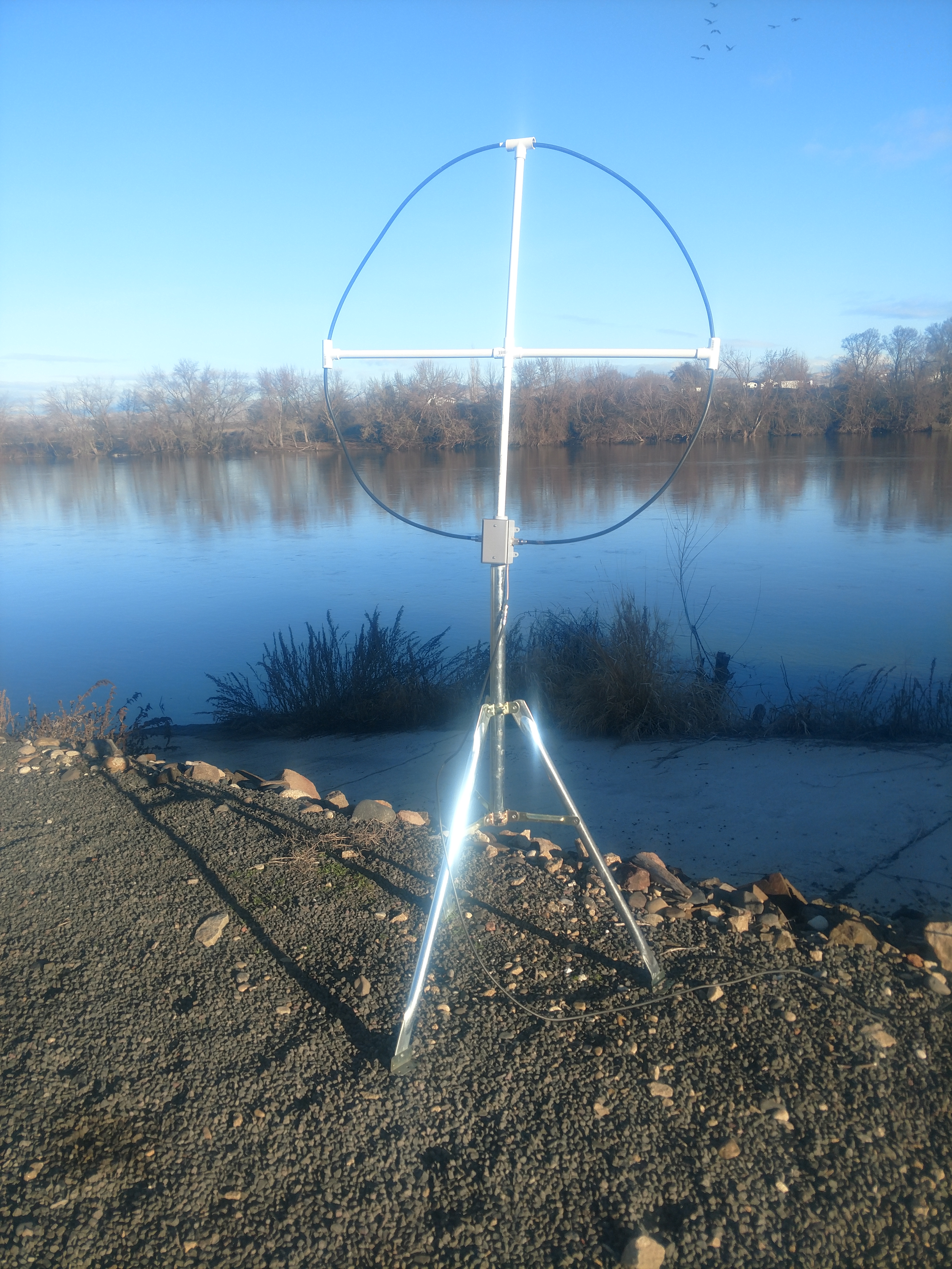
And sure enough, here is the updated version of the loop antenna. The 1/2″ PVC pipe is not glued and is depending on compression and friction to stay together. This makes it easy to take apart and use portable.

So here is an image of the waterfall shown side by side with a waterfall image of a 210′ dipole for comparison.

It occurred to me to check the relative antenna / LNA. I connected a 50 ohm load to the transmitter and set it for 5 watt carrier output. Transmitter is 100′ from the loop antenna. The loop and Hiletgo amp provided these results into the KiwiSDR.
Inspiration for experimenting and building this loop is taken from the following web sites:
https://pa0fri.home.xs4all.nl/Ant/Active%20antenna/Active%20receiving%20%20loop%20antenna%20eng.htm
https://w8ji.com/magnetic_receiving_loops.htm
http://valentfx.com/vanilla/categories/kiwisdr-discussion
https://www.nonstopsystems.com/radio/frank_radio_antenna_magloop.htm
Video discussing setting the Hiletgo LNA for best SNR. If you don’t want to watch the video, use 8 to 9vdc and you should be fine. 8vdc seems to give the lowest noise floor and 8.5vdc might be just a bit better on SNR.
Ron
KA7U


